 |
|
 |
|
'FP' Series Bandpass Filters |
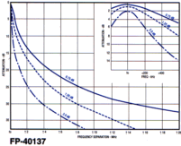
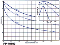
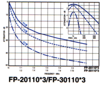
 'FP' Series Bandpass Filters 'FP' Series Bandpass FiltersSinclair's FP series cavity filters are the building blocks of the finest antenna systems. These filters pass a band of frequencies while attenuating frequencies on either side of the desired frequency band. The insertion loss of the passband may be preset at the factory or adjusted in the field.  The amount of attenuation (selectivity) can be increased by increasing the insertion loss or using multiple cavities in series. At 800 MHz and above, filter design must recognize the extremely close tolerances required to assure flawless performance over temperature when small variations in electrical wavelength mean significant changes in frequency response curves. Consequently, Sinclair engineers have carefully adapted the FP series filters for a variety of applications in the 806-960 MHz frequency range.
|
||
|
 |
|
SPECIFICATIONS |
| Electrical (Specifications) | |||||
FP-10107*3 |
FP-20107*2 |
FP-20107*3 |
FP-30107*3 |
||
| Frequency Range | MHz |
66-88 | 132-150 | 138-174 | 406-512 |
| Pass Band Insertion Loss | See Curves | ||||
| Attenuation | dB | See Curves | |||
| Maximum Input VSWR (Note1) |
1.5:1 | ||||
| Maximum Input Power Power Rating: at 0.5 dB at 1.0 dB at 1.5 dB at 2.0 dB at 3.0 dB |
Watts | 400 210 N/A N/A 90 |
350 185 80 |
||
| Termination | 'N' Female | ||||
| Temperature Range | -40�C to +60�C | ||||
FP-40137 |
FP-40103 |
||
| Frequency Range | MHz |
851-960 | |
| Pass Band Insertion Loss | See Curves | ||
| Attenuation | dB | See Curves | |
| Maximum Input VSWR (Note1) |
1.5:1 | ||
| Maximum Input Power Power Rating: at 0.5 dB at 0.75 dB at 1.0 dB at 3.0 dB |
Watts | N/A 280 N/A N/A |
125 N/A 65 30 |
| Termination | 'N' Female | ||
| Temperature Range | -40�C to +60�C | ||
| Note:1- VSWR is referenced to 50 ohms. VSWR varies with
insertion loss setting. 2- Specify transmit and receive frequencies when ordering. If unspecified, filters will be supplied untuned. 3- Typical curves for other configurations are available upon request. |
| Mechanical Specifications | |||||||
| FP-10107*3 | FP-20107*2 | FP-20107*3 | FP-30107*3 | FP-20110*3 | FP-30110*3 | ||
| Height | in (mm) | 65(1651) |
35.5(902) |
32.5(826) | 18(457) | 32.5(826) | 20(508) |
| Width | in (mm) | 7.0(178) | 7(178) | 10(254) | |||
| Depth | in (mm) | 7.0(178) | 7(178) | 10(254) | |||
| Weight | lb (kg) | 6.0 (2.7) | 11(5.0) | 10(4.54) | 6(2.72) | 15(6.8) | 8(3.63) |
| FP-40137 | FP-40103 | ||
| Height | in (mm) | 16.7 (424) |
9.5 (241) |
| Width | in (mm) | 7.0 (178) | 3.25 (83) |
| Depth | in (mm) | 7.0 (178) | 3.25 (83) |
| Weight | lb (kg) | 5.5 (2.5) | 2.0 (.91) |
|
WISCO International, Inc. -
MIAMI, FL U.S.A. Fax: (954) 370-3997 | E-mail: wiscointl@wiscointl.com |