|
|
|
|
Home Page | Manufacturers | Decibel Products | Fiberglass | Quotation | Search | E-mail |
"VARI-TILT"™
OMNI ANTENNAS WITH ELECTRICAL BEAMTILT |
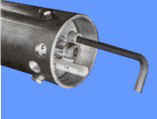
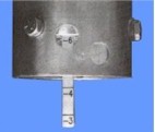
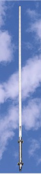 The New Industry Standard "VARI-TILT"™ Base Station Antennas (patent pending) utilize a unique design that provides an omnidirectional radiation pattern with a field adjustable Variable Electrical Beamtilt (VEB) capability. This medium gain antenna allows you to custom tailor your coverage areas by utilizing field adjustable VEB that gives a total negative beamtilt range of 3 degrees to 8 degrees below the horizon. At maximum beamtilt, more energy is focused below the main beam for null-fill resulting in enhanced close-in coverage. The beamtilt may be adjusted at the antenna even after installation, without removing the radome or the inconvenience of changing jumper cables and re-weatherproofing the connectors. The beamtilt is easily determined by viewing the Calibration Rod (which slides in and out of the antenna base) while adjusting the VEB with a hex tool (supplied). No special tools or test equipment required!
|
|
|
SPECIFICATIONS |
| Electrical | ASP-977 | ASPD975 |
| Power | 500 watts | |
| Gain | 81/2dB (� .5 dB) | 10 dB |
| Frequency Range | 806-869 MHz (ASPA977V5) 824-896 MHz (ASPD977) 872-960 MHz (ASPJ977) 872-960 MHz (ASPJ978) |
824-894 MHz |
| VSWR | 1.5:1 | |
| Impedance | 50 ohms | |
| Vertical Beamwidth | 7 degrees | |
| Horizontal Beamwidth | N/A | 240 degrees |
| Front-to-Back Ratio | N/A | 8dB |
| Beamtilt | Variable -3 to -8
degrees (ASPA977V5 (or 0 to-5 degrees) |
|
| Lightning Protection | Direct Ground | |
| Termination | N female (no lumper cable supplied) | |
| Mechanical | ASP-977 |
ASPD975 |
| Rated Wind Velocity | 165 mi/h (265 km/h) | 138 mi/h (222 km/h) |
| Equivalent Flat Plate Area | 1.75 ft� (0.16m�) | 3.5 ft" (.33 m') |
| Lateral Thrust | 70 lb (31.8 kg) | 70 lb (31.8 kg) |
| Bending Moment @ 100 mph (161 kph) |
422 Mb (58 km-m) | 1,616 ft-lb (223.4 km-m) |
| Length | 1 4.4 ft (4.38m) | |
| Weight (including clamps) | 35 Ibs (16 kg) | 45 Ibs (20.4 kg) |
| Support | 21/2 inches (7.3 cm) diameter aluminum pipe 28 inches (71 cm) long | |
| Mounting | Two (2)
ASPR616-type heavy-duty mait clamps furnished (Does not require special mounting hardware) |
|
| Shipping Information | ASP-977 | ASPD975 |
| Weight | 63 lb (28.6 kg) | 73 lb (33 kg) |
| Dimensions | 41/2 inches (11.4 cm) ODx 171 inches (345 cm) | |
| "See catalog sections for mounting brackets, coaxial cable,
connectors and other materials required for complete installation. VAPOR-WRAP* connector
sealant is included. NOTE: For antenna inversion applications, use only ASPD978 for 824-896 MHz, ASPJ978 for 824-960 MHz. |
|
WISCO International, Inc. -
MIAMI, FL U.S.A. Fax: (954) 370-3997 | E-mail: wiscointl@wiscointl.com |
Home Page | Manufacturers | Decibel Products | Fiberglass | Quotation | Search | E-mail |